

碳材烘干生产线
生产线介绍:新型立式烘干生产线采用我公司专利技术进行独特的内部结构设计,实现了物料烘干过程中与热烟气充分接触,进行折流式多次热交换,达到物料受热均匀、热效率高;碳材经过内、外筒之间的环形空间呈蠕动下落,物料之间几乎呈静止状态,有效降低了物料之间磨损的破损率。
新型立式烘干生产线不同于卧式滚动烘干机,而是采用静态烘干,整个设备处于静止状态,生产过程包括物料输送系统、干焦沫输送系统、本体烘干系统、排料系统、成品输送系统、除尘系统(碳材、成品、本体除尘)、热风系统、压缩空气、氮气、供电系统、控制系统。窑本体为整个系统的核心部分,生产中,以窑本体为核心,实现整个生产系统的全自动控制。
产能:20吨⁓50吨/小时
热源:热风炉烟气、窑尾高温烟气。


突出优势
(1)新型立式烘干生产线烘干物料单位能耗低,节能效果极其显著。
(2)烘干过程综合破损率低。
(3)烘干兰炭水分质量控制稳定。
(4)设备占地面积小。
(5)设备运行费用低:由于新型立式烘干生产线采取静置设备近似静态烘干,设备的稳定性大大提高, 烘干机物料缓慢蠕动下滑,设备磨损小。
工艺流程
(1)物料输送系统
湿兰炭从焦场通过原料皮带送至本系统湿兰炭缓冲仓顶部,另有燃料焦沫输送系统将干焦沫送至兰炭干燥系统燃料储仓内,供热风炉使用。原料皮带机根据湿兰炭缓冲仓顶部的料位高度自动补料。湿兰炭缓冲仓可容纳工艺要求的湿兰炭储量,供烘干炉自动连续生产使用。湿兰炭缓冲仓根据烘干炉料位高度通过垂直大倾角皮带自动补料至烘干炉内,湿兰炭仓与沸腾炉共用一个框架。为避免湿兰炭缓冲仓顶部皮带机尾扫料器或应急排料使用,机尾安装有垂直管道,管道末端接入焦沫燃料仓。
(2)干焦粉输送系统
干焦沫是将筛分配料站的兰炭筛下物用气力输送仓泵送至兰炭干燥界区内的燃料仓(容积满足烘干窑全部使用焦沫时的 1 天燃料用量),燃料仓大小和安装高度等进行合理设计,燃料仓顶部连接有自湿兰炭仓顶下来的垂直排料管。燃料仓下部使用物料输送装置(优先使用刮板机+圆盘给煤机方式) 将焦沫送入热风炉内。
(3)本体系统
本体系统主要接收由原料输送系统垂直大倾角皮带输送来的湿兰炭,通过接料板、布料器将湿兰炭送入烘干机。立式烘干机由外、中、内三层筒体和导流板组成,外、中筒体之间由8个隔板组成废气通道,中、内筒体组成环形物料通道。在重力的作用下,物料蠕动进入物料层中逐步进行烘干,在物料层外圈与物料层内圈的作用下,物料被均匀的分布在圆环形的物料层中且被物料层隔板分为 8 个舱室,实现对烘干机的精确控制。物料层外圈与物料层内圈在阻挡物料进出的情况下,最大可能的保证了热风的通行。
(4)热风系统
碳材烘干机主热源管道接至热风炉,旁路连接其他可利用高温烟气,当风量和温度不能满足烘干机需求时,由热风炉补充热风。空气由鼓风机送入热风炉内,通过燃烧炭材焦沫产生低温热风,热风依次通过副炉膛、分为多路风管分别从不同高度进入烘干炉内,在导气流导流板和负压原理的作用下,穿过物料层与炉内湿兰炭进行充分热交换后,带走多余水份后分多路管道进入尾部工艺除尘器内,通过净化除尘后达标排放。热风炉后的风管加装自控阀,便于根据温度调整配风量。
(5)出料系统
烘干机出料仓对应8个排料口设置电机振动给料机,通过振动给料机将成品卸如成品缓冲仓,缓冲仓底部设置电液动插板阀、双层重锤锁风阀、(气动)分料三通,将兰炭卸入成品皮带上,通过皮带机送至中转站内。为方便初始开车或炉内出现红料后及时排料, 三通的另一侧,设有一条事故皮带机,方便应急排料。
(6)除尘系统
废气除尘系统采用负压式,除尘器采用低压脉冲布袋除尘器,收集的粉尘由提升机至收尘灰仓。对于立式烘干设备,由于是采用低温烘干原理,并且热风多次穿过物料,热交换彻底,造成进入两套除尘设备的热风初始温度在70℃左右,春夏秋季节节能效果显著,但是在冬天的时候容易结露,所以除了做好除尘器外保温的前提下,从烘干机的进风口旁通一个 DN250 的热风管,连接到烘干机出风管上,中间加装电磁蝶阀,通过电磁蝶阀控制其开启度,确保在冬季时节,进入除尘器的热风温度在 90℃左右,提高了进入除尘器热气温度,避免结露;当春天来了,气温升高后关闭电磁碟阀, 所有的热风直接进入烘干机,提高热风能效。最后烟气由除尘器净化处理后经由风机、烟囱向大气排放,排放气体含尘浓度≤10mg/Nm3.
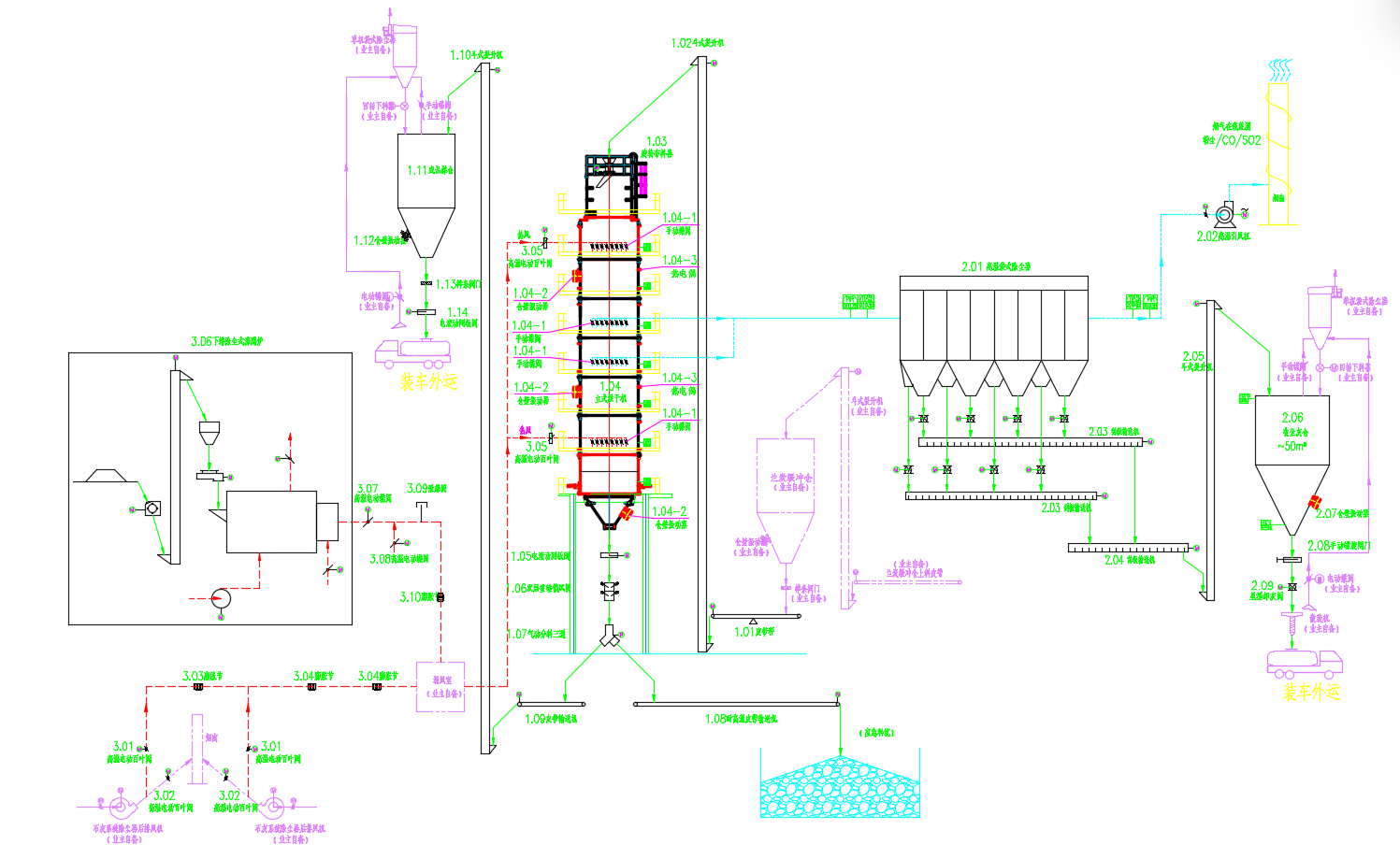
工艺流程图
技术参数
|
产能(t/h)
|
20 ⁓ 50
|
|
处理物料
|
兰炭、焦炭、电石渣、煤泥、锂电硅料
|
|
物料粒度/mm
|
5 ⁓ 35
|
|
物料初始水分/%
|
≤20
|
|
干料产品水分/%
|
≤1
|
|
破碎率/%
|
≤2
|
|
成品温度/℃
|
≤120
|
|
烟气温度/℃
|
≤85℃(进布袋除尘器前)
|
|
标准煤耗(Kg/吨)
|
≤32
|
|
干基兰炭电耗(KWh/吨)
|
≤15
|
|
烟气排放浓度(mg/Nm3)
|
≤10
|
|
年工作日天数/天
|
≥330
|
|
操作人数/(人/班)
|
2⁓3
|
免费获取更多解决方案
如果您对我们的产品感兴趣,请留下您的电子邮件,我们将尽快与您联系,谢谢!


