

加湿搅拌生产线
加湿搅拌生产线介绍:加湿搅拌生产线是一种用于加湿和搅拌工业粉料的设备,其工作原理主要包括加湿、搅拌和控制三个方面。生产线的主要设备为搅拌机,工作时,在搅拌机的外壳设有若干进水口,连接供水管道,搅拌装置的喷嘴将水喷成水雾并释放至被搅拌粉料表面,增加搅拌室内的湿度;依靠搅拌机内部的搅拌装置或刀片快速旋转,将粉状物料进行搅拌和混合。搅拌完成的湿料含有一定的水分,可通过输送机械卸至汽车的运输机械上,卸料过程无粉尘;通过控制面板,用户可以设置搅拌时间、速度和加湿程度等参数。控制面板将设置转化为电信号,控制机器的运行和加湿功能。加湿搅拌生产线具备高效、环保的特性,广泛应用于化工冶金、电力、矿山、环保、建材等行业。
产能:10吨 200吨/小时
项目现场

突出优势
(1)采用两组螺旋叶片进行搅拌,具有搅拌效率高,占地面积少。
(2)搅拌机搅拌叶片采用高耐磨特种合金或符合陶瓷,使用寿命长。
(3)设备转动平稳,噪音低。
(4)设备使用维护方便,具有高效省时的优点。
(5)系统粉尘污染低、扬尘少,作业岗位洁净环保,符合环保要求。
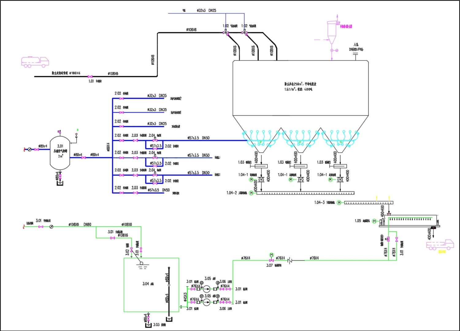
工艺流程
(1)干粉料输送系统
系统主要由:输送管路、单机袋除尘器、干粉仓等组成。罐车将干粉料由输送管路气力输送至干粉仓,仓顶设有单机袋除尘器,输送粉料的压缩空气经过滤后排至大气,排放指标满足环保要求。
(2)加湿搅拌系统
系统主要由:星型卸灰阀、螺旋输送机、加湿搅拌机等组成。在此环节,干粉料与水进行混合搅拌制成湿料。
系统开始启动时,现场操作箱按钮点击“一键启动”,首先加湿搅拌机自动启动,然后下螺旋输送机自动启动,上螺旋输送机自动启动、最后星型卸灰阀自动启动。星型卸灰阀启动延迟设定时间(根据现场调试时间进行设置)供水系电磁阀自动打开。星型卸灰阀启动前仓底卸料硫化系统自动打开。干粉料从粉仓内卸至加湿搅拌机进行加湿处理作业。
当料仓发出低料位信号时,仓底卸灰阀自动停止,系统自动执行“一键停止”程序,同时系统发出低料位报警信号。
系统需要停止工作时,现场操作箱按钮点击“一键停止”,首先星型卸灰阀自动停止;延迟设定时间后上螺旋输送机自动停止;再次延迟设定时间后下螺旋输送机自动停止;延迟设定时间供水系统电磁阀自动关闭。最后加湿搅拌机自动停止。
每台设备的起停均设置手/自动转换模式。通过频率输入调整各台设备输送量大小,其中下螺旋输送机带称重功能,每小时干物料输送量在控制界面上显示。系统压力、流量、设备运行状态均在操作界面显示。
(3)供水系统
系统主要由:水箱、水泵、电动调节阀、电磁流量计、电磁阀、供水管道等组成。
通过输入电动调节阀开度,调整供水量大小,经电磁流量计计量将结果在控制界面上显示。系统为恒压供水,当调节阀开度发生变化,系统压力与水泵进行PID调节,将系统压力维持在设定值0.3-0.8Mpa,恒压定量的水源送至加湿搅拌机外壳均布的喷水口参与搅拌作业。
水箱下限位与供水管道潜水泵、电磁阀及水泵进行连锁控制。当水箱发出低水位信号时,电磁阀打开,潜水泵启动;当水箱发出高水位信号时,潜水泵停止,电磁阀关闭;当水箱发出超低水位信号后,水泵停止工作,系统自动执行“一键停机程序”。
水泵的停启设置手/自动转换模式。通过频率输入调整水泵流量。系统压力、流量、设备运行状态均在操作界面显示。
(4)压缩空气硫化系统
干粉仓低设置硫化装置,气源通过电磁阀控制,通过时间间隔控制硫化,系统压力、流量、设备运行状态均在操作界面显示。
技术参数
| 产能(t/h) | 10 | 20 | 40 | 60 | 80 | 100 | 200 |
| 主要设备 | 主要配套设备型号及技术经济指标 | ||||||
| 螺旋直径/mm | Ø400 | Ø400 | Ø600 | Ø600 | Ø700 | Ø700 | Ø800 |
| 搅拌机功率/kw | 4.0 | 5.5 | 11 | 15 | 18.5 | 22 | 30 |
| 进水口法兰 | DN50 | DN50 | DN100 | DN100 | DN100 | DN100 | DN100 |
| 水压/MPa | 0.4 ⁓ 0.8 | ||||||
| 含水量/% | 15 ⁓ 20 | ||||||
免费获取更多解决方案
如果您对我们的产品感兴趣,请留下您的电子邮件,我们将尽快与您联系,谢谢!


